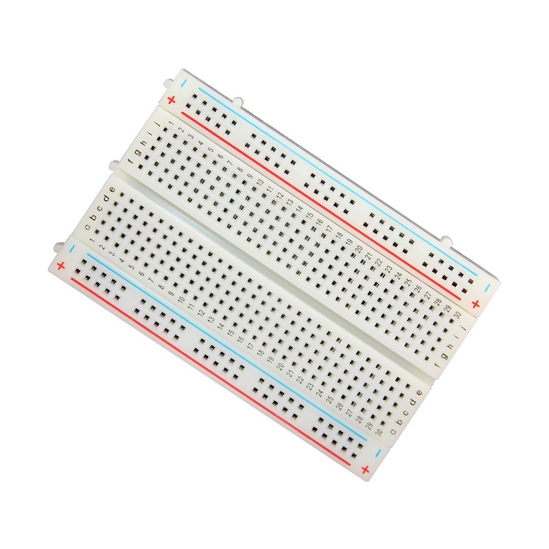
Make your own Arduino circuit on breadboard
MOHD ZAMZURI ZAKARIA 6 years ago 2501 0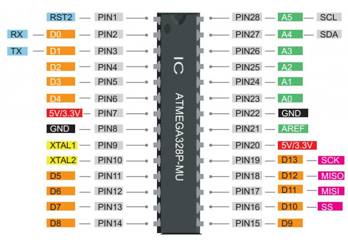
Project URL
https://seeeddoc.github.io/Hardware_Development_Kit_for_Arduino_Uno/Description
Hi, just want to share how we can make our own Arduino board on breadboard.
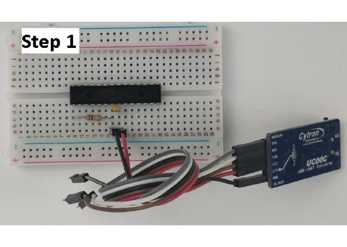
Step 1: Power
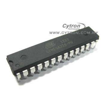
To power up Atmega328P, we need to use 5V voltage, but don't worry, we can take 5V directly from UC00C.
Connection:
Set UC00C slide switch to 5V, use Male to male jumper wire, and connect VCC from UC00C to Atmega328P pin number 7.
Take another male to male wire and connect GND UC00C to Atmega328P pin number 8.
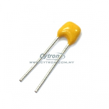
Take Multilayer capacitor 0.1uF (label as 104) and connect between pin 7 and pin 8 Atmega328P as voltage stabilizer.
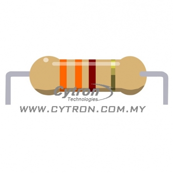
Use Resistor 10K ohm and connect between 5V and Atmega328P Pin number 1 or RESET pin to make sure RESET not pull to GND.
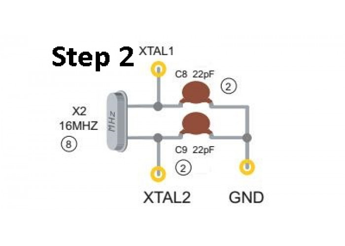
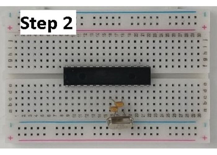
Step 2: Oscillator circuit
Oscillator or sometime called as clock or resonator is a circuit is a circuit that provide periodic signal.
Connection:
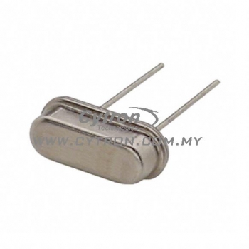
Take one Crystal 16MHz and put between pin number 9 and 10 (XTAL1 and XTAL2) on Atmega328P.
Use 2 Multilayer capacitor 22pF and connect between pin 8 (GND) and pin 9/10 (Xtal pin).
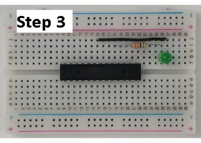
Step 3: LED circuit
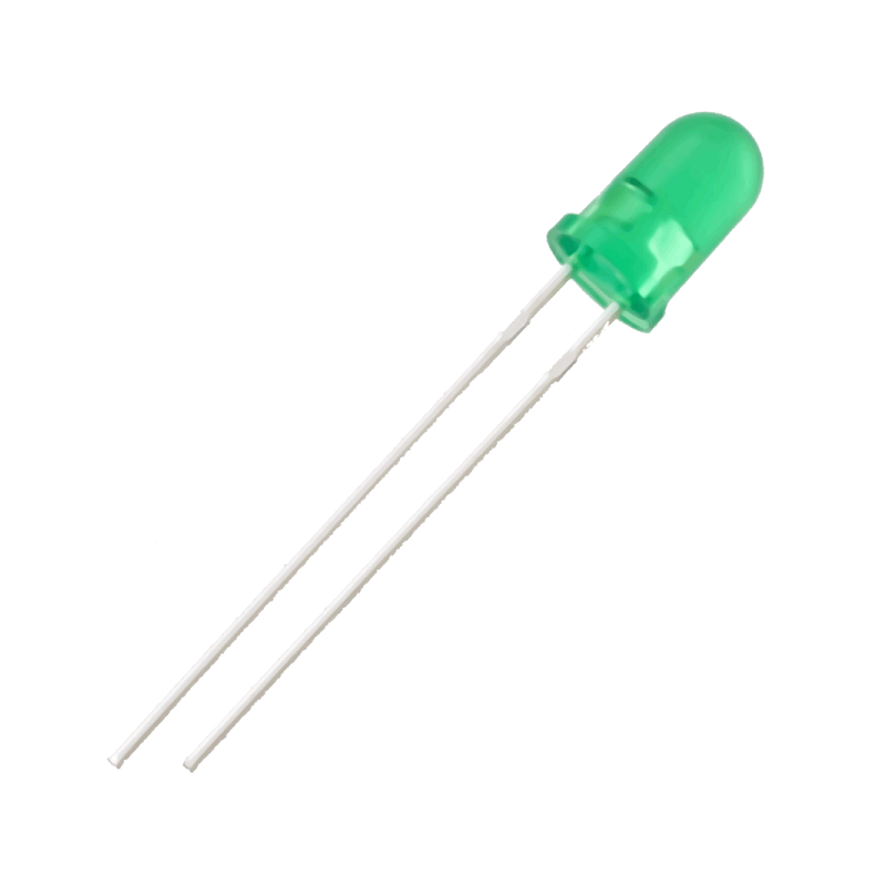
In Arduino UNO, built in LED already connected to pin number D13. LED can be used as output indicator.
In real application, Digital Output is used to turn ON relay or another actuator like motor or solenoid,
but please take note, due the current requirement, to turn ON relay or another actuator need to add another
circuit like H-Bridge motor driver circuit or as simple as one transistor.
COnnection:
Take one resistor 330 ohm and connect to pin number 19 at Atmega328P.
Another end of resistor will connect to LED positive pin (long leg).
Negative LED pin need to connected to GND pin, we can use Male to male jumper
wire to connect LED negative pin to Atmega pin number 22 (GND).
At this step, if you power up UC00C, LED should be blinking.
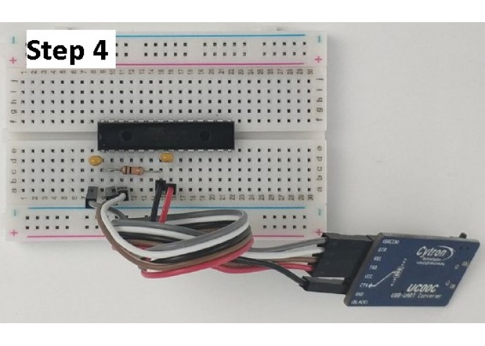
Step 4: Program Atmega328P using Arduino IDE
To make sure we can upload code using Arduino IDE to Atmega328p,
we need to make sure about:
Atmega328P already have Bootloader? TX/RX pin connected? RESET pin can go Low and High?
Atmega328P have 5V voltage?
Connection:
Connect TX pin from UC00C to Atmega328p pin number 1 (RX) using male to male jumper wire.
Connect RX pin from UC00C to Atmega328p pin number 2 (TX) using male to male jumper wire.
Connect DTR pin from UC00C to one end of Multilayer capacitor 0.1uF and connect another end
of capacitor tp Atmega RESET pin number 1.
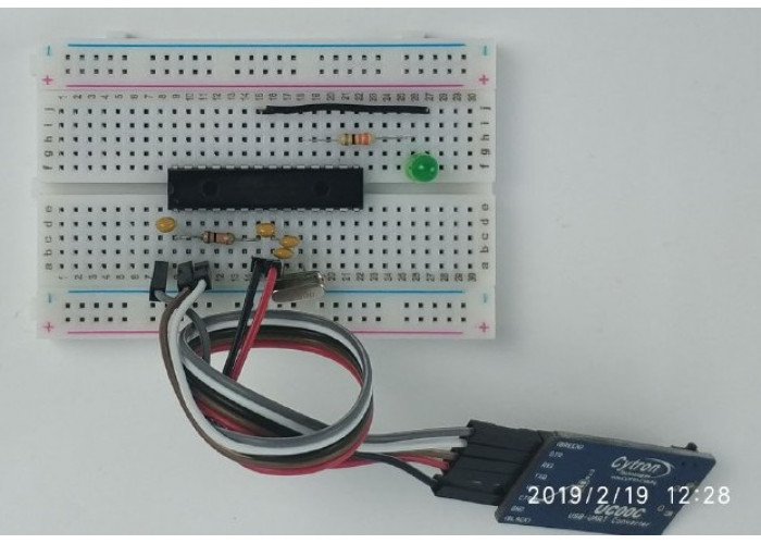
Step 5: Test Blink example code
Open your Arduino IDE on your Laptop/PC.
Go to File > Examples > 01.Basics > Blink
Connect USB cable from UC00C to your laptop.
Go to Tools, select board as Arduino/Genuino UNO
Select your COM port.
Click UPLOAD button (Arrow Button)
Change your Delay value and see the different.
*1000 delay equal to 1 second.
Parts you need for this project
-
 x 1
x 1 -
 x 1
x 1 -
 x 1
x 1 -
 x 1
x 1 -
 x 2
x 2 -
 x 2
x 2 -
 x 1
x 1 -
-600x600.jpg) x 1
x 1 -
 x 1
x 1 -
 x 1
x 1 -
 x 1
x 1